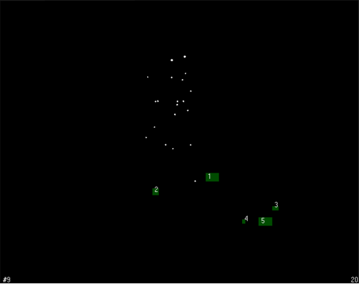
Enter 2D view and first physically remove all reflective objects, such as the calibration kit or similar reflective equipment, from the measurement volume.
- Go to the Camera settings sidebar on the right side of the 2D view. Click on Enable for Marker masks.
-
Click on “Auto-create” and start. QTM will mask all unwanted reflections. For manual masking options and advanced handling of camera settings and marker masks, please refer to the QTM Manual.
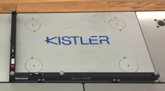
Place the L-shaped calibration reference on the floor.

|
Precise alignment is critical for the calculation of the joint moments/power. |
The correct placement depends on the convention that was used when setting up the force plates in QTM. Either the X- or Y-axis must be parallel to the intended walking direction but it does not matter whether the subject walks in positive or negative X/Y-direction.
-
The L-frame must be always placed on the same force plate, and in the same corner. We recommend that you take a picture of the default placement of the L-frame and put that picture in your lab.
-
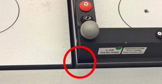
The corner of the L-frame must be placed exactly on the corner of the force plate.
-
The long axis of the L-frame must be aligned exactly with the edge of the forceplate. If your L-frame has force plate alignment aids, use them for better alignment. The alignment of the short axis is not critical.
-
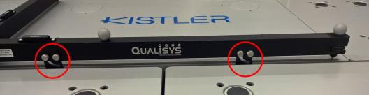
Always use height adjustment screws so that both axes are horizontal (use the spirit level gages for guidance). Avoid changing the setting of the screws between calibrations.
To calibrate, click on the calibration tool on the top menu bar.
![]()
If you use the C-Motion Caltester, now you can perform a test to ensure the L-frame was aligned correctly and the force platform settings are correct.